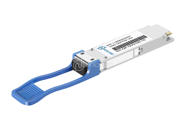
Deploying 100G links in data centres or metro networks often relies on the widely adopted 100GBASE‑LR4 QSFP28 module. This compact hot‑pluggable transceiver uses four LAN‑WDM wavelengths around 1310 nm, achieves a reach of 10 km over duplex single‑mode fibre (SMF), and incorporates digital diagnostic monitoring (DDM). Despite its standardised specifications, users frequently encounter the frustrating “plug and no link” situation. The root cause is almost always compatibility – not hardware failure. This guide explains why compatibility issues occur and provides a step‑by‑step strategy to ensure your LR4 modules work flawlessly from the first insertion.
Understanding the Compatibility Challenge
Why a “Standard” Module Can Still Be Incompatible
The QSFP28 Multi‑Source Agreement (MSA) defines mechanical, electrical, and basic management interfaces, but it leaves many implementation details open. Each networking equipment vendor (Cisco, Juniper, Arista, Huawei, etc.) may interpret or extend the MSA in proprietary ways. The most common compatibility traps come from three areas: vendor‑specific EEPROM encoding, software‑based locking (brand whitelisting), and incomplete support for digital diagnostics.
A 100GBASE‑LR4 module must report its identity, serial number, and capabilities through a memory map (defined by SFF‑8636). Some switch vendors deliberately check this data against a pre‑approved list. If the module’s vendor name or part number is not in that list, the switch may refuse to bring the interface up – even though the optics are fully compliant. This is a business decision, not a technical necessity.
Pre‑Deployment Checklist: Avoid the “Plug and No Link” Trap
Step 1 – Verify Switch Compatibility with the Exact LR4 Model
Before purchasing any LR4 transceiver, visit your switch vendor’s official compatibility matrix. For example, Cisco publishes a “Cisco Transceiver Modules Compatibility Matrix”, and Arista maintains a similar list. Search for the exact part number of the optical module you intend to use. If you are buying third‑party optics, ask the supplier for a compatibility list that has been tested on your specific switch models and software versions. Never assume that because one LR4 works, another brand will work – the EEPROM content differs.
Step 2 – Check Switch Firmware and Host Software Requirements
Even a physically compatible module can fail if the switch runs outdated firmware. Manufacturers often add new transceiver IDs in later software releases. For instance, a 100G LR4 module produced in 2025 might use a newer revision of the SFF‑8636 memory map. If your switch is running firmware from 2023, it may not recognise the module. Therefore, always upgrade the network OS to the latest stable version before installing new optics. This simple step resolves a surprising number of “unsupported transceiver” errors.
Step 3 – Confirm That DDM/DOM Is Not Blocked by Whitelisting
Digital diagnostic monitoring (DDM), also called DOM (digital optical monitoring), provides real‑time values for temperature, supply voltage, laser bias current, and optical TX/RX power. Some switch platforms disable DDM access for non‑approved modules while still allowing traffic. Others block the port completely. To avoid this, look for third‑party LR4 modules that are “coded” to match the brand of your switch. Reputable optical suppliers offer coding services – they program the EEPROM with a vendor‑approved ID (e.g., “Cisco‑compatible” or “Juniper‑compatible”). This coding tricks the switch into treating the module as a genuine one, enabling full functionality including DDM.
Testing and Troubleshooting When a Module Does Not Link
Physical Layer Checks: Fibre, Polarity, and Power Budget
A surprising number of “compatibility” problems are actually fibre plant issues. The 100GBASE‑LR4 module requires duplex LC single‑mode fibre (OS2) with a total attenuation below the maximum channel loss (typically 6 dB for 10 km). First, verify that the two fibres are not crossed (TX of module A must go to RX of module B). Second, clean both LC connectors thoroughly – a speck of dust can drop the received power below the sensitivity threshold (‑10.6 dBm for a typical LR4). Third, measure the optical loss with a power meter or use the module’s own DDM readouts to check that the receive power is within the specified range (usually between ‑10.6 dBm and +4.5 dBm).
Using Digital Diagnostics to Identify the Fault
Once the module is inserted, log into the switch and execute the command to read transceiver information (e.g., show interfaces transceiver on Cisco‑like OS, or show interfaces ethernet transceiver details on Arista EOS). If the switch does not even display the module’s serial number, the EEPROM communication has failed – either the module is defective, or the switch is actively blocking it. If the serial number appears but the interface remains down, check the alarm flags: “RX loss of signal” indicates no light arriving from the far end (fibre or far‑end TX problem); “TX fault” suggests the local laser has failed or the switch disabled it. These diagnostics guide you to the exact cause.
When All Else Fails: Enabling Third‑Party Optics via CLI
Many switch vendors allow you to override the whitelist using a hidden command. For example, on Cisco Nexus switches, the command service unsupported-transceiver followed by no shutdown forces the interface to attempt link regardless of the vendor ID. On Arista, transceiver-allow-unsupported can be configured per port. Use these with caution – they void any hardware support claim from the switch vendor, but they are a legitimate last resort. If the module still does not link after this, the issue is almost certainly physical (damaged fibre, wrong polarity, or defective module).
Best Practices for Sourcing 100G LR4 Modules
Choose Reputable Third‑Party Suppliers with Clear Compatibility Guarantees
To permanently avoid “plug and no link”, work with optical module vendors that provide three things: (1) brand‑specific coding – they will pre‑program the module to match your switches; (2) a written compatibility statement listing exact switch models and minimum firmware versions; (3) a sample loan program – they send one module for free testing before you place a bulk order. Avoid unknown sellers on marketplaces that cannot provide these assurances. A well‑coded 100G LR4 QSFP28 from a reliable third‑party supplier often performs identically to the OEM version at a fraction of the cost.
Conclusion
Compatibility issues with 100G QSFP28 LR4 modules are not random – they stem from vendor‑specific EEPROM checks, outdated firmware, or simple physical layer mistakes. By verifying the switch compatibility matrix, keeping firmware current, choosing properly coded optics, and using DDM to diagnose problems, you can achieve 100% success on the first insertion. Remember that the “plug and no link” message is almost always fixable; it rarely indicates a defective module. With the systematic approach described in this guide, you will spend less time troubleshooting and more time enjoying reliable 10‑km 100G connectivity.